Charlieplexing Arduino: Control 72 LEDs with just 9 Arduino Pins - The complete guide
Introduction
Blinking an LED 💡 using an Arduino is the “Hello World” of electronics. There are many ways to blink an LED using Arduino - 5 Ways to Blink an LED with Arduino describes at least 5 ways of blinking an LED.
Let's take a look at a basic example: 👇
void setup() {
  pinMode(LED_BUILTIN, OUTPUT);
}

void loop() {
  digitalWrite(LED_BUILTIN, HIGH);
  delay(1000);
  digitalWrite(LED_BUILTIN, LOW);
  delay(1000);
}
The code shown above will blink an LED that is connected to Arduino pin 13. But often we need to drive more than one LED.
For example, if we are driving three LEDs for a traffic light 🚥 project, it is simple and straightforward to use three Arduino port pins. But what happens if we want to use a large number of LEDs, such as a 5x5 LED matrix?
Arduino only has 20 GPIO pins that we can use, so using one pin per LED won't do the trick for us. That's a shame because a 5x5 LED matrix can display numbers, symbols and letters and could be a great addition to our next Arduino project.
Fortunately, there are other, more pin-efficient ways to connect LEDs to Arduino. Charlieplexing is one of the less-known methods to solve this problem: it enables controlling many LEDs with just a few Arduino pins!
You are going to learn how it works. By the end of this article, you will have a clear understanding of how Charlieplexing works, as well as how to code and wire the hardware with full confidence 😎.
LED There be Light 💡
A standard LED has two connections: Anode (+) and Cathode (-). You can make it emit light by applying positive voltage to the LED's Anode, and negative voltage to the Cathode.
The amount voltage you need varies between LED of different colors and types, and is called "forward voltage". For standard 5mm red LEDs, the forward voltage will be between 1.6 volts to 2 volts.
The LEDs also have a certain current limit (usually around 20mA). Hence, you should use a resistor to make sure only the desired amount of current flows through the LED (or else, it may suffer and die!).
Charlieplexing Makes it Possible?
With Charlieplexing, we can drive up to 6 LEDs using just three pins. How does that work? In short, we're taking advantage of a limitation of the human eye: when multiple LEDs are sequentially lit one after the other rapidly, it will appear as all of them are lit at the same time.
This is called "Persistence of Vision" (PoV in short).
Here are some popular examples of what you can create using this technique (and Charlieplexing):
- Your own matrix display driver
- Rolling display board
- Clock with 60 LEDs around the clock to tell the hour, minute and second hands
- Chessboard which is bottom lit – 64 LEDs
- LED Cubes – beautiful 3D cube made out of 8x8x8 LEDs (512 in total)
How many LEDs can you drive with a given number of pins?
Short answer: many!
For an exact number, check this table out:
| Number of Pins | How many LEDs can you drive? |
|---|---|
| 2 | 2 |
| 3 | 6 |
| 4 | 12 |
| 5 | 20 |
| 6 | 30 |
| 7 | 42 |
| 8 | 56 |
| 9 | 72 |
| n | n * (n-1) |
In general, you can drive n*(n-1) LEDs using n pins. This is the number of ways
of selecting 2 items out of n different items. For more info about the math, take a
look at the Wikipedia article.
You are still here? Great, let's see how Charlieplexing is done in practice. We'll start from a simple Arduino design with two-port pins and work our way up to nine-port pins!
The best way to learn is by doing. Hence, we will use Wokwi's Online Arduino Simulator, meaning you will be able to run all the examples in your browser.
Why not just build the circuit with real LEDs? Trust me, you don't want to sit for hours checking the wiring for 72 LEDs and scratching your head, just to figure out that you have plugged some LEDs in the wrong direction or have some loose wires.
When learning (and prototyping), I believe it's best to isolate the software from the hardware. Thus, the simulation environment gives you working hardware, so you can focus on learning the concept and reduce the risk of issues.
Once you understood how Charlieplexing works and have the code running in the simulator and doing once you want, then yes, I encourage you to go ahead and build the hardware. This way, you can minimize frustration and maximize the fun! 😁
As you follow the rest of the tutorial, you'll be able to run the code on Wokwi's Arduino playground with simulated LEDs, verify the code, build confidence, and when you are ready, also build the physical circuit with the tested-and-tried software. Let's get going!
Light'em Up!🏇
All our examples will follow this principle: the common goal will be to be able to individually control each LED, turn it on for a moment, and then turn it off. Eventually, code should cycle through all the LEDs.
Case 1: Charlieplexing 2 LEDs with 2 Arduino pins
We'll start with the most basic example: just 2 LEDs.
The Cathode of the LED(2,3) is connected to Arduino pin 2 and Anode of the LED is connected to Arduino pin 3.
Similarly, The Cathode of the LED(3,2) is connected to Arduino Pin 3 and Anode of the LED is connected to Arduino Pin 2.
Circuit diagram
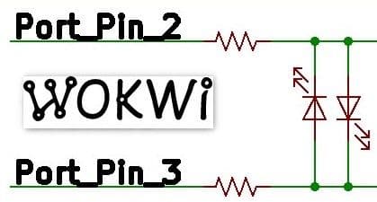
Here is what our code will be doing:
- Set pin 2 as OUTPUT pin
- Set pin 3 as OUTPUT pin
- To turn LED(2,3) ON a. Drive logic LOW on pin 2 b. Drive logic HIGH on pin 3
- To turn LED(3,2) ON a. Drive logic HIGH on pin 2 b. Drive logic LOW on pin 3
- Repeat steps 3-4 endlessly
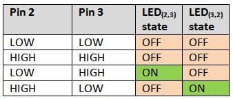
Tips: The LEDs need to have a similar forward voltage drop to be able to drive all of the LEDs with equal brightness. If you have LEDs of the same color and type, it should do the trick 😉 . Also, when building this circuit, you'll need one current limiting resistor for each used Arduino pin.
You can have a look at the output of the simulation taken from Wokwi Arduino playground:
Arduino Code: Basic 2 LED control with Charlieplexing
This is the code we ran in the simulation. The green markers explain more about the code - move your mouse over those lines (or tap them) to see the extra information:
/* Charlieplexing example: 2 pins driving 2 LEDs. */

#define SCAN_DELAY 500

void setup() {
}

void loop() {
  pinMode(2, OUTPUT);
  pinMode(3, OUTPUT);
  digitalWrite(2, LOW);
  digitalWrite(3, HIGH);

  // Keep LED on for SCAN_DELAY milliseconds:
  delay(SCAN_DELAY);

  pinMode(2, INPUT);
  pinMode(3, INPUT);

  pinMode(2, OUTPUT);
  pinMode(3, OUTPUT);
  digitalWrite(2, HIGH);
  digitalWrite(3, LOW);
  delay(SCAN_DELAY);
  pinMode(2, INPUT);
  pinMode(3, INPUT);
}
But wait! What's the benefit of this code? You could have connected two Arduino Pins to two LEDs and drive them directly, and the code would be much simpler.
In reality, you won't be using Charlieplexing when you just need to drive 2 LEDs. It doesn't make sense. But I included this example to explain the basic logic behind Charlieplexing. Let's see how we can generalize this code so that it works for any number of pins:
Code Summary: Generalizing Charlieplexing!
We looked at 2 specific examples above:
- To turn on LED(2,3), we set pin 2 LOW and pin 3 HIGH
- To turn on LED(3,2), we set pin 3 LOW and pin 2 HIGH
Now, let's look at the generalized version of how we can control Charlieplexed LEDs:
- Set all pins to
INPUT. - Turning on LED(x,y):
- Configure pins x and y as
OUTPUT. - Drive pin x
LOWand pin yHIGH.
- Configure pins x and y as
- Turning off LED(x,y): configure pins x and y as
INPUT.
In the previous code example, we tried to keep the code simple and easy to understand. The downside is that you cannot easily expand the code for three (or more) pins.
So now, we're going to rewrite the code. It'll still do the same, but make it easier for us to extend later:
/* Charlieplexing example: 2 pins driving 2 LEDs with loops. */

#define SCAN_DELAY 500

byte LED_PINS[] = { 2, 3 };
const byte LED_PIN_COUNT = sizeof(LED_PINS);

void setup() {
}

void loop() {
  for (byte i = 0; i < LED_PIN_COUNT; i++) {
    for (byte j = 0; j < LED_PIN_COUNT; j++) {
      if (i != j) { //The LED port pins are always connected to two different pins
        pinMode(LED_PINS[i], OUTPUT); //port 2
        pinMode(LED_PINS[j], OUTPUT); //port 3
        digitalWrite(LED_PINS[i], LOW);
        digitalWrite(LED_PINS[j], HIGH);
        delay(SCAN_DELAY);
        pinMode(LED_PINS[i], INPUT);
        pinMode(LED_PINS[j], INPUT);
      }
    }
  }
}
Case 2: Driving six LEDs with three Arduino Pins-Charlieplexing
3 pins ⇒ 3 * 2 = 6 LEDs.
Circuit Diagram
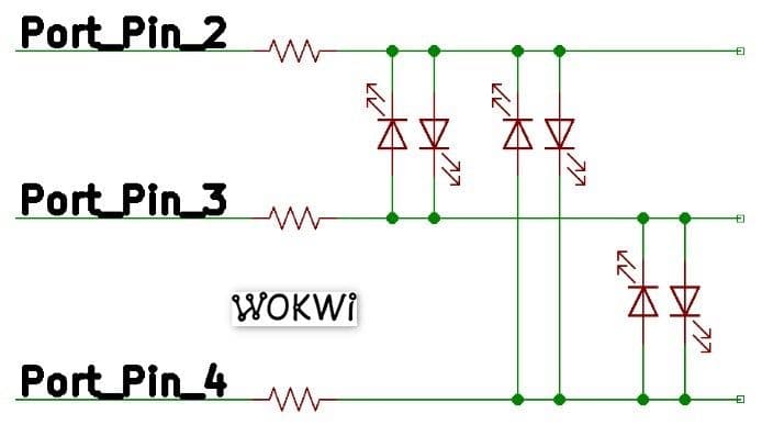
And the 6 LEDs arranged as follows:
Arduino code
/* Charlieplexing example: 3 pins driving 6 LEDs. */

#define SCAN_DELAY 500

byte LED_PINS[] = { 2, 3, 4 };
const byte LED_PIN_COUNT = sizeof(LED_PINS);

void setup() {
}

void loop() {
  for (byte i = 0; i < LED_PIN_COUNT; i++) {
    for (byte j = 0; j < LED_PIN_COUNT; j++) {
      if (i != j) {
        pinMode(LED_PINS[i], OUTPUT);
        pinMode(LED_PINS[j], OUTPUT);
        digitalWrite(LED_PINS[i], LOW);
        digitalWrite(LED_PINS[j], HIGH);
        delay(SCAN_DELAY);
        pinMode(LED_PINS[i], INPUT);
        pinMode(LED_PINS[j], INPUT);
      }
    }
  }
}
Code Summary
Since we made our code modular, we only had to change a single place: add the
new pin number (4) to the LED_PINS[] array.
Case 3: Driving twelve LEDs with four Arduino Pins-Charlieplexing
4 pins ⇒ 4 * 3 = 12 LEDs.
Circuit Diagram
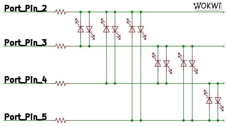
You have 12 LEDs in this case
· LED(2,3), LED(2,4), LED(2,5),
· LED(3,2), LED(3,4),LED(3,5),
· LED(4,2), LED(4,3), LED(4,5),
· LED(5,2), LED(5,3), LED(5,4)
Arduino code
/* Charlieplexing example: 4 pins driving 12 LEDs. */

#define SCAN_DELAY 500

byte LED_PINS[] = { 2, 3, 4, 5 };
const byte LED_PIN_COUNT = sizeof(LED_PINS);

void setup() {
}

void loop() {
  for (byte i = 0; i < LED_PIN_COUNT; i++) {
    for (byte j = 0; j < LED_PIN_COUNT; j++) {
      if (i != j) {
        pinMode(LED_PINS[i], OUTPUT);
        pinMode(LED_PINS[j], OUTPUT);
        digitalWrite(LED_PINS[i], LOW);
        digitalWrite(LED_PINS[j], HIGH);
        delay(SCAN_DELAY);
        pinMode(LED_PINS[i], INPUT);
        pinMode(LED_PINS[j], INPUT);
      }
    }
  }
}
Case 4: Driving 20 LEDs with five Arduino Pins-Charlieplexing
5 pins ⇒ 5 * 4 = 20 LEDs. Wiring starts to get complex, but the code will still be pretty much the same.
Circuit Diagram
You have 20 LEDs in this case:
Arduino code
/* Charlieplexing example: 5 pins driving 20 LEDs. */

#define SCAN_DELAY 500

byte LED_PINS[] = { 2, 3, 4, 5, 6 };
const byte LED_PIN_COUNT = sizeof(LED_PINS);

void setup() {
}

void loop() {
  for (byte i = 0; i < LED_PIN_COUNT; i++) {
    for (byte j = 0; j < LED_PIN_COUNT; j++) {
      if (i != j) {
        pinMode(LED_PINS[i], OUTPUT);
        pinMode(LED_PINS[j], OUTPUT);
        digitalWrite(LED_PINS[i], LOW);
        digitalWrite(LED_PINS[j], HIGH);
        delay(SCAN_DELAY);
        pinMode(LED_PINS[i], INPUT);
        pinMode(LED_PINS[j], INPUT);
      }
    }
  }
}
Case 5: Driving 30 LEDs with six Arduino Pins-Charlieplexing
6 pins ⇒ 6 * 5 = 30 LEDs. Just one more pin, and we can control 10 more LEDs. Isn't that fun?
Circuit Diagram
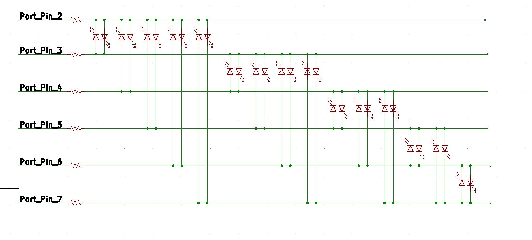
And the LEDs:
The code was omitted for brevity. We basically add the number 7 at the end of the
LED_PINS array.
Case 6: Driving 42 LEDs with 7 Arduino Pins-Charlieplexing
7 pins ⇒ 7 * 6 = 42 LEDs. So with just 7 pins, we can convey the meaning of the universe in LEDs! 🌎
Circuit Diagram
One universe, 42 LEDs. Please don't forget your towel!
We will get back to discussing the code shortly.
Case 7: Driving 56 LEDs with 8 Arduino Pins-Charlieplexing
8 pins ⇒ 8 * 7 = 56 LEDs. And we're not even done - there's one more pin down the road.
Circuit Diagram
56 LEDs for your pleasure below. We made the animation a bit faster now, otherwise it'd be too boring ;-)
And if you want to try it yourself, just head over to our Charlieplexing playground and give it a spin! Experimenting yourself is key to learning.
Case 8: Driving 72 LEDs with 9 Arduino Pins-Charlieplexing
You've made it to the last example! Actually, I was too lazy to draw the connection diagram here (it gets very tedious as the number grows). But I'm pretty sure at this point you got the idea...
You have 72 LEDs in this case:
Arduino code
Did you notice something different about the LEDs above? It seems like they are all on even though we're lighting them up one at a time, just as we did before.
So what's the trick?
/* Charlieplexing example: 9 pins driving 72 LEDs. */

#define SCAN_DELAY 1

byte LED_PINS[] = { 2, 3, 4, 5, 6, 7, 8, 9, 10 };
const byte LED_PIN_COUNT = sizeof(LED_PINS);

void setup() {
}

void loop() {
  for (byte i = 0; i < LED_PIN_COUNT; i++) {
    for (byte j = 0; j < LED_PIN_COUNT; j++) {
      if (i != j) {
        pinMode(LED_PINS[i], OUTPUT);
        pinMode(LED_PINS[j], OUTPUT);
        digitalWrite(LED_PINS[i], LOW);
        digitalWrite(LED_PINS[j], HIGH);
        delay(SCAN_DELAY);
        pinMode(LED_PINS[i], INPUT);
        pinMode(LED_PINS[j], INPUT);
      }
    }
  }
}
A side effect of this method is that the LEDs will be much dimmer. In fact, each LED is lit only 1/72 of the time. The solution is simply to light one row at a time, Instead of one LED at the time. This way, each LED will get power for ~1/9 of the time:
/* Charlieplexing example: 9 pins driving 72 LEDs with row-scanning. */

#define SCAN_DELAY 1

byte LED_PINS[] = { 2, 3, 4, 5, 6, 7, 8, 9, 10 };
const byte LED_PIN_COUNT = sizeof(LED_PINS);

void setup() {
}

void loop() {
  for (byte i = 0; i < LED_PIN_COUNT; i++) {
    pinMode(LED_PINS[i], OUTPUT);
    digitalWrite(LED_PINS[i], LOW);
    for (byte j = 0; j < LED_PIN_COUNT; j++) {
      if (i != j) {
        digitalWrite(LED_PINS[j], HIGH);
        pinMode(LED_PINS[j], OUTPUT);
      }
    }
    delay(SCAN_DELAY);
    for (byte j = 0; j < LED_PIN_COUNT; j++) {
      digitalWrite(LED_PINS[j], LOW);
      pinMode(LED_PINS[j], INPUT);
    }
  }
}
In fact, by changing the code a little bit and adding an if condition, we could
display any pattern you want. Check out the explanation in the green marker above
for more information.
When to use Charlieplexing?
- Charlieplexing is best suited where you need to drive only a few LEDs at a time
- You can display almost any pattern by quickly turning the LEDs on and off, but your MCU will be working hard.
- The brightness of the LED may go down or become uneven when we are driving many LEDs at the same time
- If the leakage current of the MCU is high, the LEDs might still be lit (poorly, but still visible in the dark) when the pins are configured as an input. Also, beware of enabling the built-in Pull-up / Pull-down resistors!
- Debugging the hardware and wiring gets really clumsy as the number of LEDs grows
- Instead of Charlieplexing, you can use external shift registers/multiplexers. The code will be simpler, the connections will be more straightforward, but you'd need these extra hardware parts.
That was it! If you have any questions, feel free to drop me an email.